IT8500 Series DC Loads communication driver is the driver to communicate with electronic load controller IT8511, IT8512, etc of ITECH Electronic Co,. Ltd. in Korea.
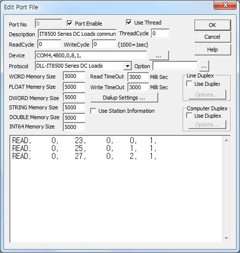
<Figure 1> is read setting example of IT8500 Series DC Loads communication driver.
|
|
| <Figure 1> Read setting example of IT8500 Series DC Loads communication driver |
Device part of <Figure 1> input Com Port(COM1), Baud Rate(4800), Parity Bit(0), Data Bit(8), Stop Bit(1) respectively, according to controller.
Note) IT8500 Series DC Loads controller normally communicate with USB device. So, you must install ‘PL2303_Prolific_DriverInstaller_v1417.exe’ program for virtual serial port.
( ‘PL2303_Prolific_DriverInstaller_v1417.exe’ program is provided by the manufacturer of IT8500 series controller )
IT8500 Series DC Loads communication driver read schedule
Read schedule setting parameters are as follows:
1) Station – 0 ~ 254 controller station number.
2) Read Command – Command = 23, 25, 27, 29, 2B, 2D, 2F, 31, 33, 35, 37, 39, 3B, 3D, 3F, 41, 57, 59, 5F. ( refer to <Table 1> )
3) Read Start Address – Don't care.
4) Save start address for Communication Server – Saving start address of Communication Server.
5) Read Size – Fixed to 1, according to read command fixed real read size. ( refer to <Table 1> )
Read schedule example)
READ, 0, 23, 0, 0, 1,
READ, 0, 25, 0, 1, 1,
READ, 0, 27, 0, 2, 1,
<Table 1> is data saving address and contents of IT8500 Series DC Loads communication driver.
<Table 2>, <Table 3> are operation state and demand state of each bit for 5F read command.
| Read command | Contnetns | Data saving address and contnets |
| 23 | Read of Max Setup Input Voltage | Start Add + 0 : Max Setup Input Voltage |
| 25 | Read of Max Setup Input Current | Start Add + 0 : Max Setup Input Current |
| 27 | Read of Max Setup Input Power | Start Add + 0 : Max Setup Input Power |
| 29 | Read of Operation Mode | Start Add + 0 : Operation Mode(0 = CC, 1 = CV, 2 = CW, 3 = CR) |
| 2B | Read of CC Mode Current | Start Add + 0 : CC Mode Current |
| 2D | Read of CV Mode Voltage | Start Add + 0 : CV Mode Voltage |
| 2F | Read of CW Mode Watt(Power) | Start Add + 0 : CW Mode Watt |
| 31 | Read of CR Mode Resistance | Start Add + 0 : CR Mode Resistance |
| 33 | Read of CC Mode Transient Current | Start Add + 0 : Setting A Current Start Add + 1 : Timer A Value(0.1 mSec unit) Start Add + 2 : Setting B Current Start Add + 3 : Timer B Value(0.1 mSec unit) Start Add + 4 : Trnasition Mode(0 = Continues, 1 = Pulse, 2 = Toggled) |
| 35 | Read of CV Mode Transient Voltage | Start Add + 0 : Setting A Voltage Start Add + 1 : Timer A Value(0.1 mSec unit) Start Add + 2 : Setting B Voltage Start Add + 3 : Timer B Value(0.1 mSec unit) Start Add + 4 : Trnasition Mode(0 = Continues, 1 = Pulse, 2 = Toggled) |
| 37 | Read of CW Mode Transient Power(Watt) | Start Add + 0 : Setting A Power Start Add + 1 : Timer A Value(0.1 mSec unit) Start Add + 2 : Setting B Power Start Add + 3 : Timer B Value(0.1 mSec unit) Start Add + 4 : Trnasition Mode(0 = Continues, 1 = Pulse, 2 = Toggled) |
| 39 | Read of CR Mode Transient Resistance | Start Add + 0 : Setting A Resistance Start Add + 1 : Timer A Value(0.1 mSec unit) Start Add + 2 : Setting B Resistance Start Add + 3 : Timer B Value(0.1 mSec unit) Start Add + 4 : Trnasition Mode(0 = Continues, 1 = Pulse, 2 = Toggled) |
| 3B | Read of List Operation Mode | Start Add + 0 : List Operation Mode(0 = CC, 1 = CV, 2 = CW, 3 = CR) |
| 3D | Read of List Repeat Mode | Start Add + 0 : List Repeat Mode(0 = Once, 1 = Repeat) |
| 3F | Read of Number of List Steps | Start Add + 0 : Number of List Step |
| 41 | Read of One of The Step’s Current | Start Add + 0 : Appointed One Step Start Add + 1 : Current Value of current step Start Add + 2 : Timer Value(0.1 mSec unit) of current step |
| 57 | Read of Remote Sense Mode | Start Add + 0 : Remote Sense Mode(0 = Disable, 1= Enable) |
| 59 | Read of Trigger Source | Start Add + 0 : Trigger Source(0 = Keypad, 1 = External, 2 = Command) |
| 5F | Read of Input Voltage/Current/Power/Relative State | Start Add + 0 : Actual Input Voltage Start Add + 1 : Actual Input Current Start Add + 2 : Actual Input Power Start Add + 3 : Operation State, refer to <Table 2> Start Add + 4 : Demand State, refer to <Table 3> |
| <Table 1> Data saving address and contents of IT8500 Series DC Loads communication driver | ||
| Bit position | Contents | Remarks |
| 0 | CAL(Calculate the New Demarcate Coefficient) | |
| 1 | WTG(Wait for Trigger Signal) | |
| 2 | REM(Remote Control Signal) | |
| 3 | OUT(Output State) | |
| 4 | LOCAL(Local Button State) | 0 = Not in Effect, 1 = in Effect |
| 5 | SENSE(Remote Testing Mode) | |
| 6 | LOT(For Load On Timer State) | |
| 7 | … | |
| <Table 2> Operation state of each bit for 5F read command | ||
| Bit position | Contents |
| 0 | RV(Input Reverse Voltage) |
| 1 | OV(Over Voltage) |
| 2 | OC(Over Current) |
| 3 | OP(Over Power) |
| 4 | OT(Over Temperature) |
| 5 | SV(Not Connect Remote Terminal) |
| 6 | CC(Constant Current) |
| 7 | CV(Constant Voltage) |
| 8 | CP(Constant Power) |
| 9 | CR(Constant Resistance) |
| A ~ F (10 ~ 15) |
… |
| <Table 3> Demand state of each bit for 5F read command | |
IT8500 Series DC Loads communication driver store the same data in WORD, DWORD, FLOAT memory, but the data format are different.
If you click the icon ![]() in protocol option part, you
can see the dialogue box such as <Figure 3>. you can also set read schedule by
using this part.
in protocol option part, you
can see the dialogue box such as <Figure 3>. you can also set read schedule by
using this part.
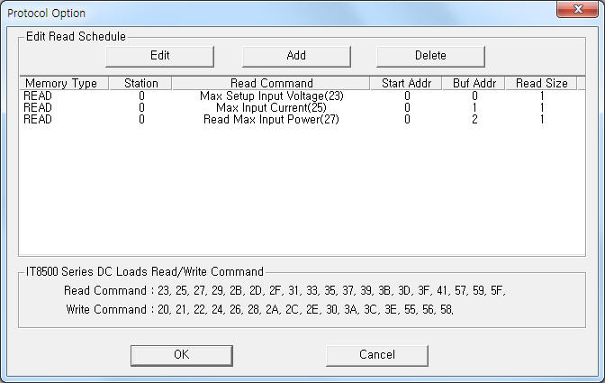 |
| <Figure 2> Example of IT8500 Series DC Loads communication driver’s Option dialog box |
You can set read schedule by using ![]() ,
, ![]() ,
, ![]() button and listbox of <Figure
2>.
button and listbox of <Figure
2>.
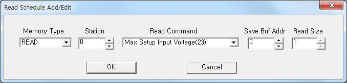 |
| <Figure 3> Example of IT8500 Series DC Loads communication driver’s read schedule Add/Edit dialog box |
When you click Add button or Edit button in dialogue box of <Figure 2>, dialogue box of <Figure 3> is shown.
You can set IT8500 Series DC Loads controller by using 'writing settings'.
Digital Write
Digital write and analog write have the same setting parameters except output value(0 or 1).
Analog Write
Analog write setting parameters are as follows:
1) PORT Port no. (0 ~ 255)
2) STATION 0 ~ 254 controller station number.
3) ADDRESS Don't care.
4) Extra1 Write command = 20, 21, 22, 24, 26, 28, 2A, 2C, 2E, 30, 3A, 3C, 3E, 55, 56, 58. ( refer to <Table 4> )
5) Extra2 Don't care.
<Table 4> is writing range and contents for write command.
Write command |
Contents |
Writing range |
20 |
Setting of Remote Control Mode |
0 = Front Panel Operation Mode, 1 = Remote Operation Mode |
21 |
Setting of Input State |
0 = OFF, 1 = ON |
22 |
Setting of Max Input Voltage |
Setting of Voltage 3 decimal point |
24 |
Setting of Max Input Current |
Setting of Current 4 digit decimal point |
26 |
Setting of Max Input Power |
Setting of Power(Watt) 3 digit decimal point |
28 |
Setting of Operation Mode |
0 = CC Mode, 1 = CV Mode, 2 = CW Mode, 3 = CR Mode |
2A |
Setting of CC Mode Current |
Setting of CC Mode Current 4 decimal point |
2C |
Setting of CV Mode Voltage |
Setting of CV Mode Voltage 3 decimal point |
2E |
Setting of CW Mode Watt(Power) |
Setting of CW Mode Watt 3 decimal point |
30 |
Setting of CR Mode Resistance |
Setting of CR Mode Resistance 3 decimal point |
3A |
Setting of List Operation Mode |
0 = CC Mode, 1 = CV Mode, 2 = CW Mode, 3 = CR Mode |
3C |
Setting of List Repeat Mode |
0 = Once, 1 = Repeat |
3E |
Setting of Number of List Steps |
Setting of List Step number( by WORD unit) |
55 |
Setting of Local Control Mode |
0 = Disable, 1 = Enable |
56 |
Setting of Remote Sense Mode |
|
58 |
Setting of Trigger Source |
0 = Keypad, 1 = External, 2 = Command |
| <Table 4> Writing range and contents for write command | ||
Note) To control of IT8500 Series DC Loads, you have to set 'Remote Control Mode'.
If the controller don't set ‘Remote Control Mode’, you can change 'Control Mode' by write command that the setting parameter = 'Output Value : 1', 'Extra1 : 20'.
Also, when turn on the IT8500 Series DC Loads controller, the default 'Control Mode' isn't 'Remote'.
Write example 1)
PORT:0, station:0, ADDRESS:0000, Extra1: 20, Extra2 : 0, Output value = 1,
The setting parameter shown above is 'Remote Control Mode' setting example for 0 station IT8500 Series DC Loads controller.
Write example 2)
PORT:0, station:0, ADDRESS:0000, Extra1: 22, Extra2 : 0,
The setting parameter shown above is ‘Max Input Voltage’ setting example for 0 station IT8500 Series DC Loads controller.
Write example 3)
PORT:0, station:0, ADDRESS:0000, Extra1: 24, Extra2 : 0,
The setting parameter shown above is ‘Max Input Current’ setting example for 0 station IT8500 Series DC Loads controller.
Write example 4)
PORT:0, station:0, ADDRESS:0000, Extra1: 28, Extra2 : 0,
The setting parameter shown above is ‘Operation Control Mode’ setting example for 0 station IT8500 Series DC Loads controller.
Block Write
IT8500 Series DC Loads communication driver don't support 'Block Write'.
Please connect USB communication cable that is provided by by the manufacturer.
You can communicate with virtual serial(RS-232C) port by ‘PL2303_Prolific_DriverInstaller_v1417.exe’ program. ( ‘PL2303_Prolific_DriverInstaller_v1417.exe’ program is provided by the manufacturer of IT8500 series controller )
<Figure 4> is appearance of IT8500 Series DC Loads controller.
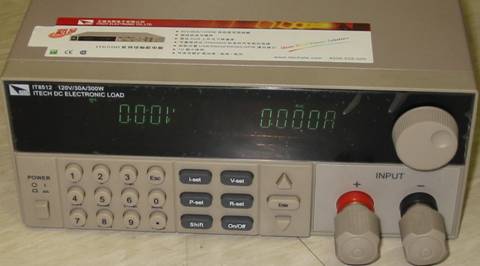 |
| <Figure 4> Appearance of IT8500 Series DC Loads controller |